Draft it Help System
The complete Help system for Draft it is available on these pages.
Available in: FREE, Plus, Pro and Architectural
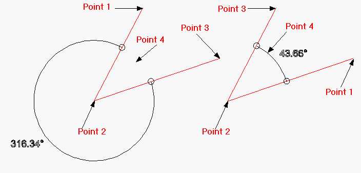
This command creates an angular dimension between 3 points. The dimension always measures the angle counter-clockwise from the 1st point to the 3rd point with the 2nd point being the corner of the angle.
Select the 'Angular Dimension' button
 and the Ribbon changes to show the current dimension properties.
You can change any of these settings whilst you are creating the dimension. The command prompt reads:
Give First Point:
Select the first point of the line using any of the snaps and input options. A dynamic line will be drawn from this point to the cursor. The prompt now reads:
Give Corner Point:
Select the second point of the line using any of the snaps and input options. The angular dimension is drawn from the line between this point and the 1st point to the cursor. The prompt now reads:
Give Second Point:
Select the second point of the line using any of the snaps and input options. The measurement of the angle is now complete and only the position of the dimension is required. The prompt now reads:
Give Dimension Position:
Select the position of the dimension using any of the snaps and input options. The dimension will be drawn and is complete.
The example below shows how the order with which the points are selected dictates the dimension appearance.

To edit an Angular dimension see Modifying/Moving Dimensions.
