Draft it Help System
The complete Help system for Draft it is available on these pages.
Available in: PRO & Architectural
Layouts and Sheets are used to offer greater flexibility to printing and drawing output requirements.
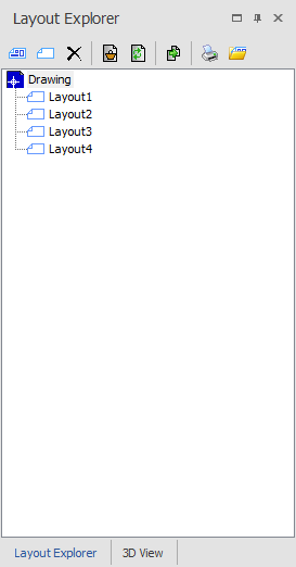
The Layout Explorer allows creation and modification of drawing layouts and sheets. A drawing layout is a view of all or part of a drawing with the option to include additional items specific to the layout. A drawing sheet is a new view that can have 'Viewports' of the original drawing placed inside of it as well as newly drawn features. A Draft it drawing can contain any number of layouts or sheets. An entity can be in any number of layouts. Entities on the main drawing cannot be modified when viewing a layout, only entities actually drawn in the layout (which do not appear in the the main drawing).
You can see in the picture to the left the Layout Explorer window. The top section contains the various command icons for layout manipulation and the lower part shows the layout content of the active drawing (icons for the drawing and for four layouts)..
Clicking on a layout name in the list changes the display in the Drawing area to show that layout. To switch back to the drawing simply click on 'Drawing' in the list.
The buttons in the Layout dialog box are:-'New Sheet', 'New Layout', 'Delete', 'Show layout Contents', 'Update layout Contents', 'Copy layout', 'Print Layouts' and 'Import Sheets'.
To create a sheet simply click on the 'New Sheet' button and you will have the option to create a new sheet at any paper size. None of the entities from the original drawing will be copied to a new sheet when it is created. You will be able to add 'Viewports' to the sheet by pressing the 'Add Viewport' button, 'Viewports' show views of the original drawing and draw other new features in the new sheet.
A 'Viewport' is a window that includes all or some of the drawing features in the main drawing or 'Model Space' as it is sometimes called. These windows can be manipulated in width and height just as you would do with a Rectangle.
The 'Import Sheets' button allows you to import sheets from any other Draft it file that you have saved that contains sheets, this can be a very useful tool that eliminates repeatedly drawing common border items like scale bars for example.
The drawing displayed inside a 'Viewport' can be zoomed in and out by selecting the viewport then holding down the shortcut keys
 +
+
 then scrolling with the mouse wheel forward and backward.
You can also pan the 'Viewports' content by selecting the viewport then holding down the shortcut keys
 +
+
 and the middle mouse button.
You can change the visibility of layers inside the 'Viewport' by selecting the viewport then clicking on the middle mouse button inside of the 'Viewport', this will bring up the context menu then you can click on the 'Set Layer Visibility' option to make alterations.
If the 'Viewport' is selected then you will see a section in the properties explorer called 'Scale Factor', you can use this option to select a different scale to use for the entities inside of the 'View Port'.
To create a layout simply click on the 'New Layout' button. Only the entities selected at the time are included in the layout, if no entities are selected then you will have the option to create a new layout where the entire drawing contents are included in the layout.
Layouts are automatically named 'Layout1', 'Layout2' and so on. It is possible to rename a Layout, click on the layout to rename then click on it again and type in the new name.
To delete a layout or sheet, select it in the layout list and click on the 'Delete Layout' button.
The 'show layout contents' button is used to select the entities stored in a layout. Click on a layout in the list and it is displayed. Click on the 'show layout contents' button and Draft it returns to the whole drawing and highlight (selects) the entities currently stored with that layout.
To update a layout use any of the Draft it methods to Select Items to add to or remove from the selection. Once the entities required for the view are selected click the 'Update layout contents' button and select the layout name to update from the list.
The 'Copy layout' button creates a duplicate of the currently selected layout or sheet, the new item is named 'Copy of Layout1' (If the original item was Layout1).
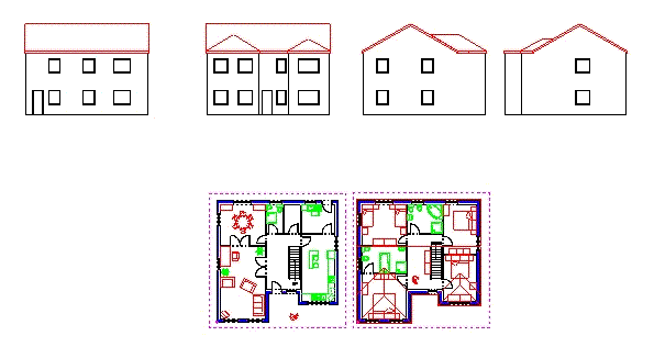
To explain further what is possible lets look a the example picture below. This is an A0 size sheet at a 1:50 scale containing a plan and 4 elevation views of a building. The rectangle around the outside is Draft it Sheet Border.
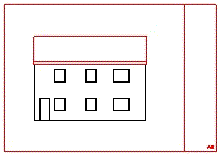
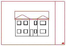
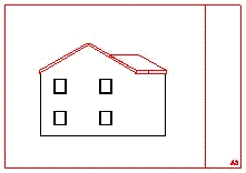
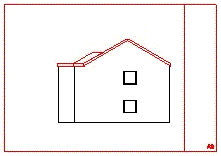
It is easy to see the requirement that the entire drawing would need to be printed, however it might also be the case that each floor plan and each elevation would be require to be on its own printed sheet, with information specific to that sheet. This is possible with layouts as the Draft it Print command only considers the currently selected display in the layout explorer when calculating what is to be printed. The layout explorer here shows a total 7 layouts have been created. One for each elevation and plan and another for both plans together.
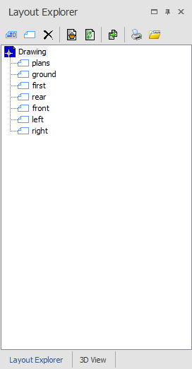
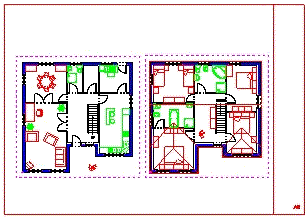
Clicking on 'plans' in the layout list changes the display to that shown below.
So this layout was created when both plan views were selected then whilst the 'plans' layout was the current display an A2 sheet border was added.
This means that the sheet border is only displayed and can only be modified when this particular layout is selected. The rest of the entities (the plans) can only be edited when the 'drawing' is the current view.
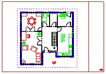
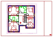
In the video below we will see an example of how to create a 'New Sheet' and to add a 'Viewport' to the sheet. We will also see how 'Viewports' can be manipulated to suit your requirements.
