Product Documentation
Draft it Help
Select the category below to quickly find the help you need.

Available in: Architectural
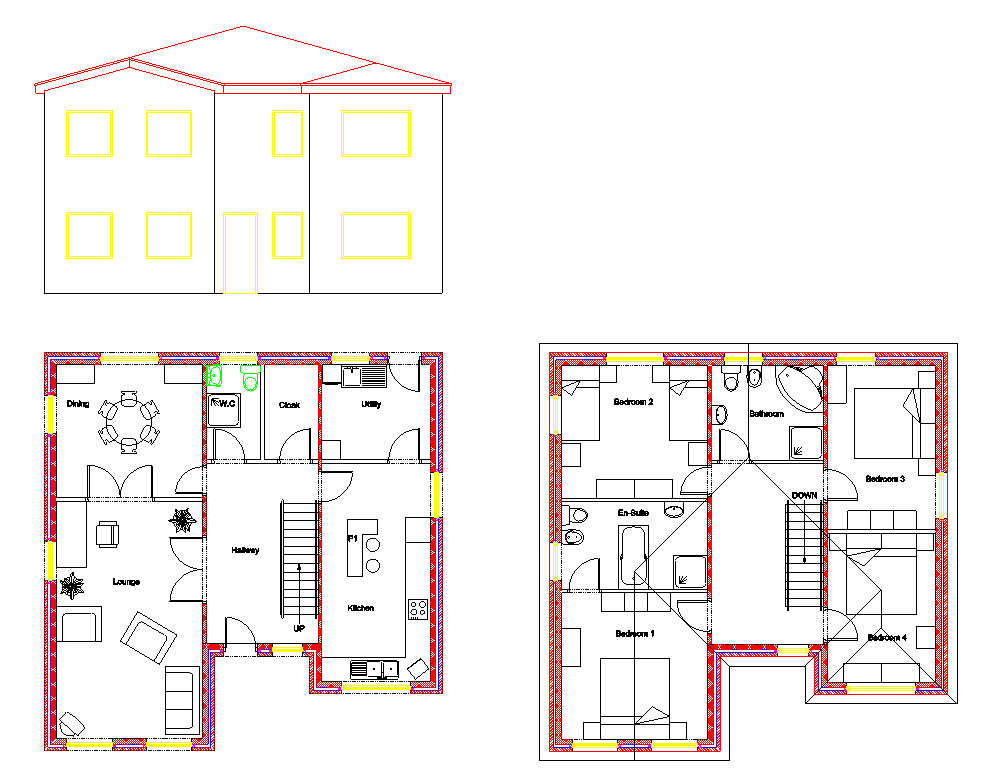
We will now create an front elevation view of the house. As this is a two story building each elevation will be created separately. First we will create the elevation of the ground floor. Select the
 Elevation button and the command prompt reads:
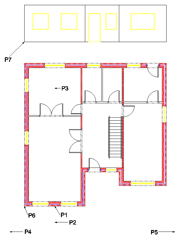
Give wall on which elevations will be based:
Simply click on the wall the elevation is to be based, in this case P1 on the ground floor. The command prompt reads:
Give observation point for elevation:
This point defines the viewing position, imagine you are standing at this point (P2) and looking at P1, so move the cursor down from P1 to P2 and click. The command prompt reads:
Give Depth of field:
This point determines how far through the building the command looks for relevant entities. We need to indicate P3, this is past the roof ridge line so the whole roof will be included but not past the rear wall so that the doors and windows in that wall are not included. The command prompt reads:
Give left extent of elevation:
We require our elevation to show the complete extents of the front aspect so click on P4 past the left hand wall. The command prompt reads:
Give right extent of elevation:
Click at P5 past the right hand wall. The command prompt reads:
Give reference point on plan:
This point is the reference point for positioning the elevation on the drawing, click at P6 (Zoom in to ensure the correct point is selected if required). The command prompt reads:
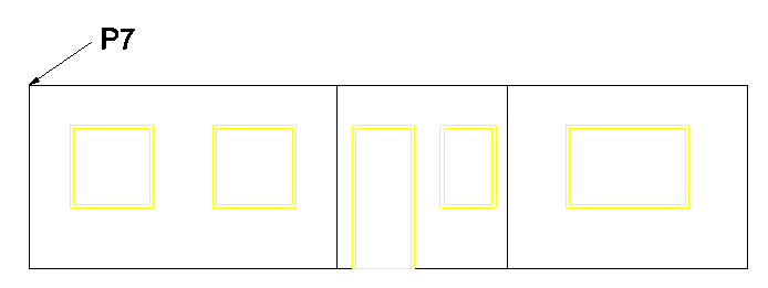
Give position of reference in elevation:
Now click at P7 to position the elevation (you can hold down the
 key here to assist lining up the this point with the last point P6).
Select the
 Elevation button again to create the first floor elevation.
The points required to create the elevation of this floor are virtually the same as the ground floor except they are selected on the first floor plan.
Elevation button again to create the first floor elevation.
The points required to create the elevation of this floor are virtually the same as the ground floor except they are selected on the first floor plan.
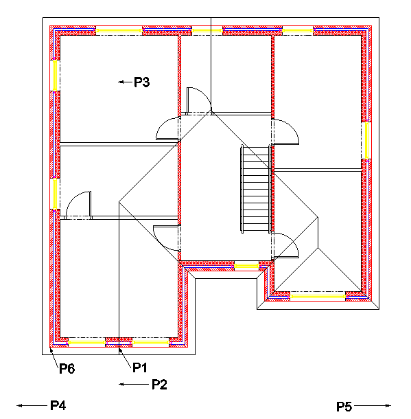
Give wall on which elevations will be based:
Simply click on the wall the elevation is to be based, in this case P1 on the first floor. The command prompt reads:
Give observation point for elevation:
This point defines the viewing position, so move the cursor down from P1 to P2 and click. The command prompt reads:
Give Depth of field
This point determines how far through the building the command looks for relevant entities. Indicate P3. The command prompt reads:
Give left extent of elevation:
We require our elevation to show the complete extents of the front aspect so click on P4 past the left hand wall. The command prompt reads:
Give right extent of elevation:
Click at P5 past the right hand wall. The command prompt reads:
Give reference point on plan:
This point is the reference point for positioning the elevation on the drawing, click at P6 (Zoom in to ensure the correct point is selected if required, especially on this floor to make sure a point on one of the roof lines is not selected). The command prompt reads:
Give position of reference in elevation:
Now to position the elevation simply click on the 'End'
![]() point at P7.
point at P7.
All that remains to do is to delete the floor/ceiling lines between the ground and first floor as shown below (highlighted as blue lines).
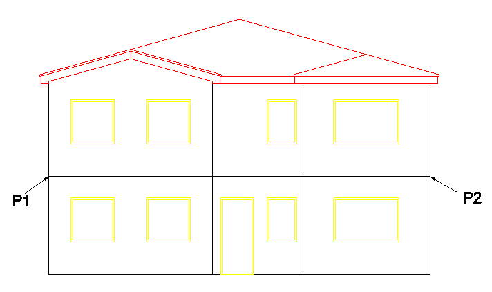
You can delete the six lines (remember there are co-incident ceiling and a floor lines) one by one. The quicker way is to click at approximately P1 and drag a box to P2, then release the mouse.
In doing this a Window selection box has picked all of the entities completely within the box. Now press
 key.
key.
The house drawing in now complete and should look like the picture below.
Any questions?
Perhaps you need help deciding which of our CAD systems is right for you, or maybe you need to chat with us about our bespoke development service.
Don’t hesitate to get in touch. The Draft it team is dedicated to ensuring you get the best design experience on the market. Whatever you need - call us, email us – we’re here to help.
 +44 1543 419 886
 enquiries@cadlogic.com
 Postal Address Details