Product Documentation
Draft it Help
Select the category below to quickly find the help you need.

Available in: FREE, Plus, PRO & Architectural
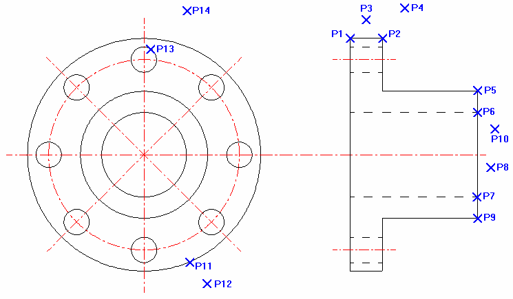
Finally we can add the dimensions to complete this tutorial drawing. As you will see the diagram has a series of points which we will use to position the dimensions.
Select the Linear Dimension button
 and the prompt reads:
Give First Point:
Select the 'End' point at P1. The prompt now reads:
Give Second Point:
Select the 'End' point at P2. The prompt now reads:
Give Dimension Position:
Select near to P3 to place the dimension.
Repeat the command to place linear dimensions between P1 & P5 positioned at P4, between P6 & P7 positioned at P8, between P5 & P9 positioned at P10.
Select the Diameter Dimension button
 and the prompt reads:
Give Arc/Circle:
Click on the circle at P11.
Give Dimension Position:
Click at P12 to position the diameter dimension.
Repeat the command to place another diameter dimension on circle P13 positioned at P14.
Click on the linear dimension at P8, the entity handles are displayed and the Annotation Group is displayed showing all of the dimension settings. We need to add a 'Ø' symbol to this dimension. Click on the 'Copy Ø' button next to the 'prefix' field (this copies that character to the clipboard. Now left-click into the 'prefix' field (this makes it the current field) and now right-click in this field and select 'Paste'. The diameter symbol 'Ø' appears in the field. Click back in the drawing area and the dimension is updated and deselected.
Note: Use the numeric keypad on the keyboard when typing in the ACSII code.
Repeat this procedure for the linear dimension at P10.
Now click on the diameter dimension at P14. Click in the 'Suffix' field and enter:-
'_Equi-spaced_on_Ø80.00_PCD' (The '_' character represents a space. Use the 'Copy Ø' button as described before to get the diameter symbol.)
Note: If this dimension clashes with the first two dimensions added then select it and use the blue Entity Handle near to the dimension text to re-position it.
The drawing is complete and now should appear as at the start of the tutorial.
Any questions?
Perhaps you need help deciding which of our CAD systems is right for you, or maybe you need to chat with us about our bespoke development service.
Don’t hesitate to get in touch. The Draft it team is dedicated to ensuring you get the best design experience on the market. Whatever you need - call us, email us – we’re here to help.
 +44 1543 419 886
 enquiries@cadlogic.com
 Postal Address Details