Product Documentation
Draft it Help
Select the category below to quickly find the help you need.

Available in: Architectural
Use this command to draw walls. Select the 'Walls' button
 and the following dialog box appears.
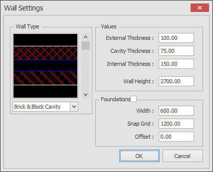
Use the scroll bar or drop down list to select the wall type. Set the values as required, these are (depending on the type selected).
External Thickness Thickness of the external wall leaf for cavity wall types or the total wall thickness of 'stud' and 'block' walls.
Cavity Thickness - Size of the wall cavity.
Internal Thickness - Thickness of the internal wall leaf for cavity wall types.
Wall Height - Not used in this version.
Foundations - (not included if the box is left unchecked)
Foundation Width - This is the width of the foundation detail.
Foundation Depth - This is the depth of the foundation detail.
Foundation Offset - This is the offset of the foundation detail
Once all of the settings are correct click OK. The dialog box closes and the command prompt reads:
Give Start Point:
Select the first end point of the wall using any of the snaps and input options and the command prompt reads:
Give Next Point:
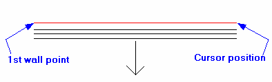
A dynamic set of lines (2 or 4 depending on the wall type selected) representing the first wall segment will be drawn from this point to the cursor. In addition to this an arrow is displayed to identify the external face of the wall, see below.
During wall drawing the Ribbon displays the following additional options.
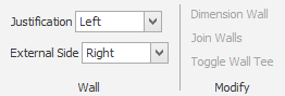
Whilst drawing walls these settings can be changed. 'Justification' can be set as either Left, Centre or Right. This is the position of the cursor in relation to the wall (in the direction of the wall).This line is displayed with a red colour for easy identification. 'External Side' can be set as Right or Left. This allows the outside face to be 'flipped' as required to either side of the wall. As with justification 'Left' and 'Right' is in relation to the direction of the wall. Therefore using these settings allow walls to be drawn either clockwise or counter clockwise to outer face, centre line or inner face dimensions.
Select the next point of the wall using any of the snaps and input options.
TIP: Use Arrow Key Input to quickly draw orthogonal walls.
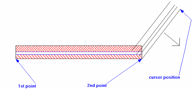
The second point is selected the 1st wall segment is drawn and a dynamic wall is drawn from the second point to the cursor position, see below
The command prompt continues to read 'Give Next Point' and you can add further walls as required. Once two walls have been drawn (i.e. 3 points have been selected) two
further options are available, 'Close' and 'Square' . Both of these options close the current wall profile back to its starting point. To 'Close' simply
type
 , this draws a wall from the cursor position to the first point indicated. If
 is typed then the wall profile is 'squared off', i.e. a horizontal and
a vertical wall are drawn back to the first point indicated.
is typed then the wall profile is 'squared off', i.e. a horizontal and
a vertical wall are drawn back to the first point indicated.
Note: The wall hatching can be switched on and off using the hatching toggle in the view pull-down menu.
See Modifying/Moving a Wall for information on how an walls can be edited, joined, dimensioned and how to add wall dimensions.
Any questions?
Perhaps you need help deciding which of our CAD systems is right for you, or maybe you need to chat with us about our bespoke development service.
Don’t hesitate to get in touch. The Draft it team is dedicated to ensuring you get the best design experience on the market. Whatever you need - call us, email us – we’re here to help.
 +44 1543 419 886
 enquiries@cadlogic.com
 Postal Address Details